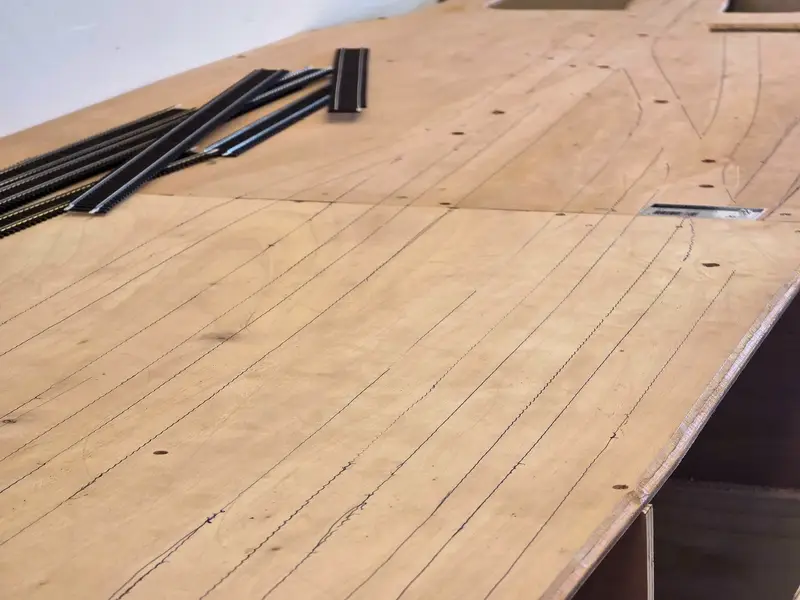
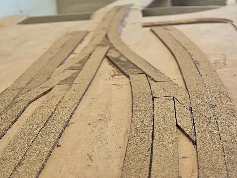
After the warm weather of the past few weeks, it was finally time to get back to work. Once I approved the test layout, I could start laying the tracks for real. The first step was to trace around the tracks so I could glue the cork neatly in the right place.
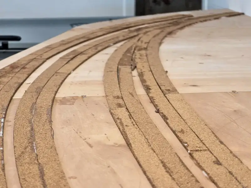
For the cork, I used strips 3 mm thick and 2 cm wide. Two strips together create the right height and width for a nice ballast bed.
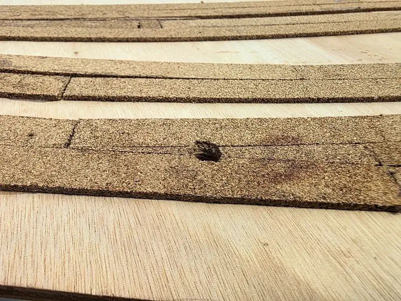
Before removing the tracks, I marked the holes for the servo operation at the turnouts. I use caps from Magica Miniatura to guide the spring steel and keep the slot minimal without too much hassle. These are the steps I followed:
- Position the turnout blades in the middle setting.
- Drill a small hole with a 1 mm drill bit through the turnout throw bar so the center point is visible on the wood.
- After removing the turnout, enlarge the center point with a 10 mm drill bit.
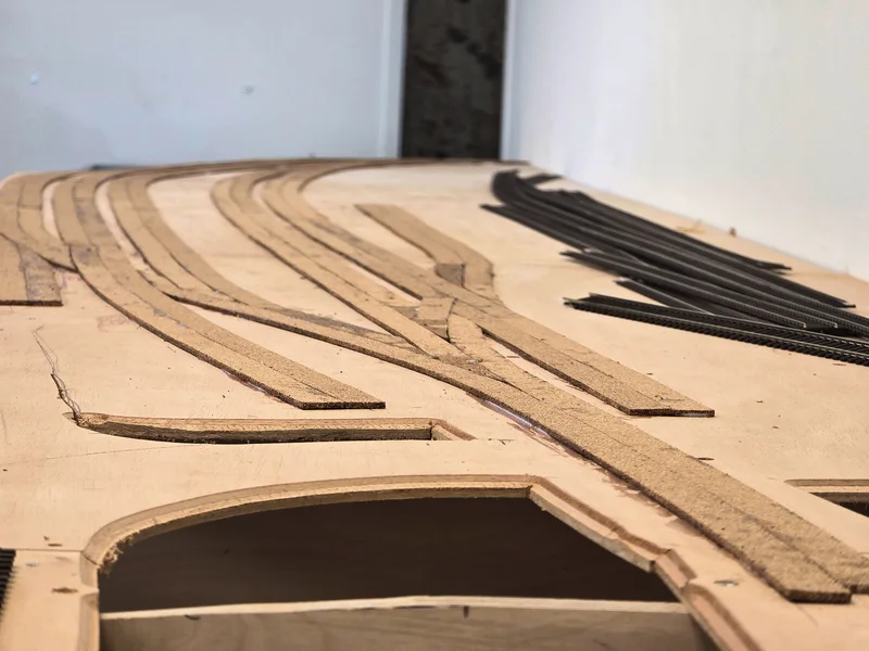
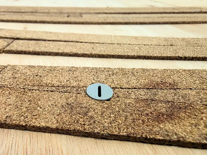
- Apply the cork, and after it dries, make the hole in the cork as well.
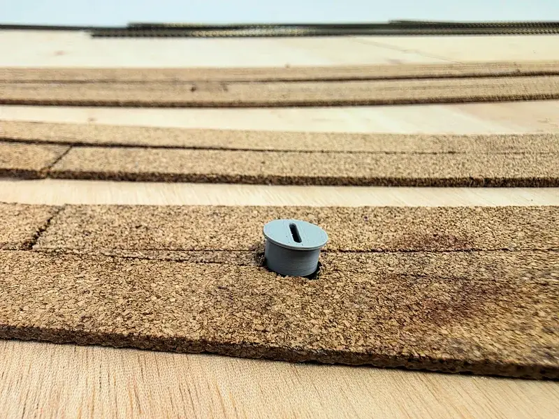
- Press the cap into the hole.
- Adjust the slot so it runs parallel to the turnout throw bar.
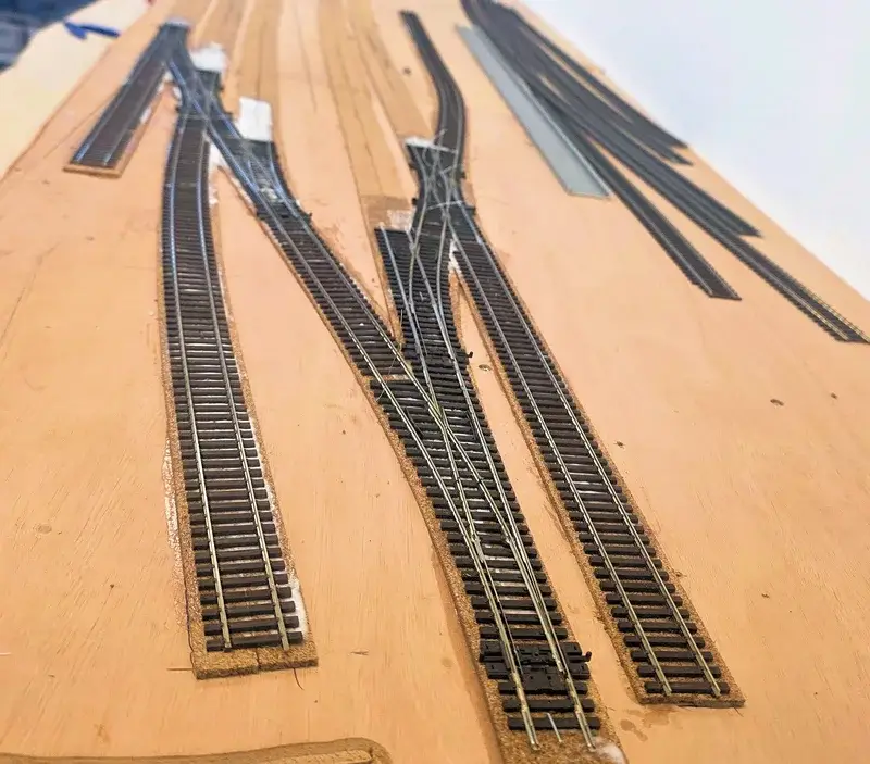
Applying the cork is always a fun puzzle. I first glue down a number of strips using flexible glue from Scape Supplies. The product is called MifoTack. The advantage of this glue is that it dries slowly and offers good immediate adhesion due to its suction effect. Once dry, the glue is completely transparent, flexible, and yet strong enough that removing it won’t happen without damaging the underlying wood. In other words, a chisel or multitool is required. On the other hand, you can easily get the tracks loose from the cork again.
I often lay the strips from the outside in, cutting out overlapping parts so they fit together.
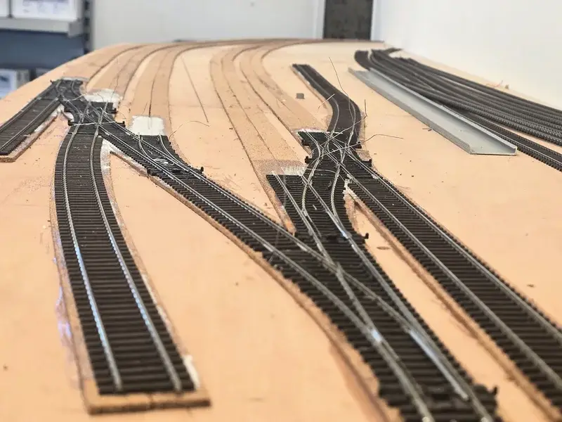
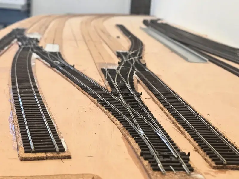
Once the glue has dried and the servo caps are in place, you can glue in the turnout throat. I always do one turnout throat first so it sets the dimensions for the rest. Aligning is precise work, but the glue gives you plenty of time to make adjustments calmly.
Before I could put the Peco turnouts in place, I removed the springs from the throw bar so the servo can move the blades nice and smoothly. I also cleared the frog wires so they’ll be usable later and aren’t glued down around the turnout.
Unlike many online reports, I never modify the turnouts. In all my years as a professional builder, I’ve never done this and never had to when using servos. Cutting into the blades to isolate the frog is a solution for incorrectly set timing of the frog relay. It’s only useful to do this if you’re using magnets or microswitches.
After the turnouts were in place, I fixed them with a staple, which is removed once the glue has cured. The next step is the opposite turnout throat and the tracks in between. Placing the signals is also coming up, so I can drill the holes for the bases.