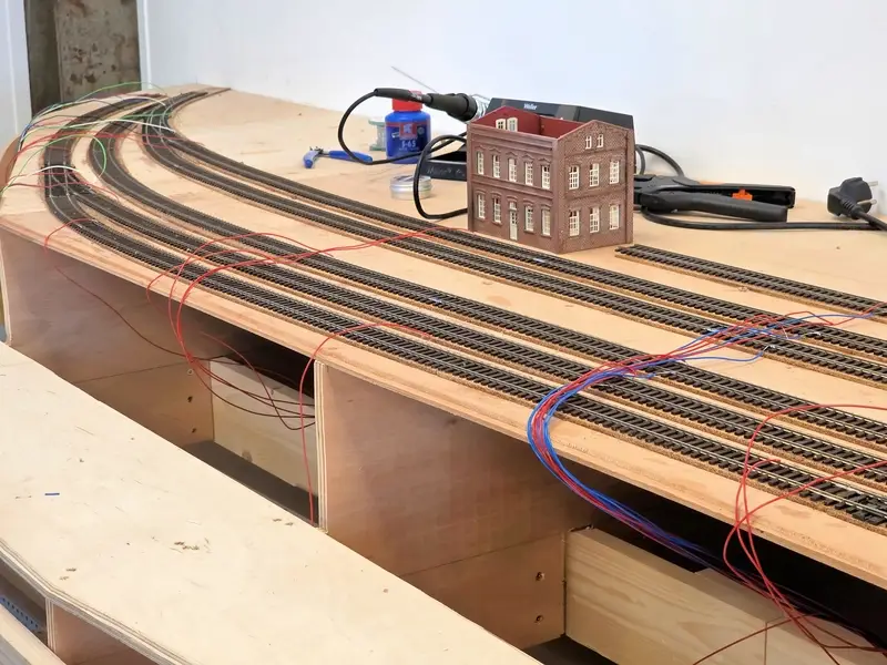
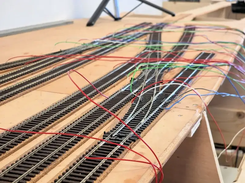
Now that the rails are glued in the station, it’s high time to apply the wiring for the blocks, sensors, and turnout polarization. In my daily work at Domburg Train Support building automated model layouts, I’ve learned a few tricks to minimize the chance of errors and keep efficiency optimal. It boils down to the fact that I’ve learned to stop thinking.
Sounds strange, but it’s actually very logical; it’s a technique from control engineering. People make mistakes when they have to think about the actions they need to perform. By eliminating all factors you might have to think about beforehand while carrying out the work, you eliminate the chance of errors and increase production speed.
To explain this, we can look closely at this example. You might think you need to determine beforehand where blocks, sensors, and gaps should be placed and where the electronics will go. These are factors you can eliminate with a few simple techniques.
Step 1: Showing your colors
The first step is choosing the colors you want to use. There is a standard choice of 11 colors:
- Red
- Blue
- Yellow
- Green
- Black
- White
- Grey
- Brown
- Orange
- Pink
- Purple
Basically, we choose colors that make the function of the wire logical. Everyone has a certain association with a color and its function. So we choose a specific color for each function and stick to the rule of thumb that the colors must contrast. For example, red and brown for the rails is a poor choice; under the layout with less visibility, they are easily confused with each other. Whereas black and white, for instance, minimize that chance. At that point, you don’t have to think about which color has which function.
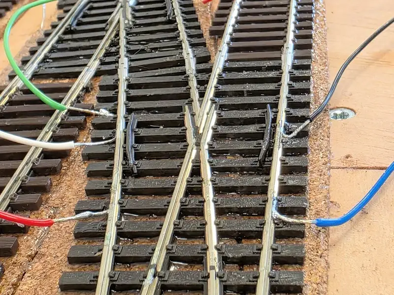
On my model layout, I chose 5 colors for the rails.
Rail A > Continuous rail: Blue
Rail B > Occupancy sensors: Red
Frog polarization turnout > Frog: Green
Frog polarization turnout > Curved rail: White
Frog polarization turnout > Straight rail: Black
You can find more about frog polarization here
In terms of wire thickness, I use 0.2 mm2 flexible wire for the rails; I’ll tell you which diameters you can use when in this tutorial.
Step 2: Length of the wires
How long should the wires be? A question I get often. And in a way, it’s a waste of time unless you want to watch the costs. For me, wire is a consumable product, and using a meter more costs me less than being a centimeter short. So I like to work with excess length in my wiring.
Because this model layout stands quite high on its legs, I don’t really feel like working above my head to connect the modules. I’ve chosen to place the electronics on a wall positioned horizontally along the underside. The average wire length will then be 2 to 3 meters long. Now, my rule of thumb is that I never make the rail wires longer than 4 meters. In this case, I can very easily choose to make every wire 4 meters long, so I can see later where I’ll place the tech.
Also, don’t worry about labeling the wires or drawing wiring diagrams. Personally, I can’t stand diagrams and drawings. They’ve deceived me so often that it takes more time than it’s worth. Writing errors, typos, differences in interpretation, or no disciplined revision of the drawings. I often throw them straight into a corner. For me, there are only two factors that speak the truth: A multimeter and the control software.
If I later measure the wires one by one with a multimeter on a continuity setting, then I know 100% for sure that it really is that wire and the connection is also fine. Working from a diagram or a label again gives a chance of reading errors, assumptions, and interpretation mistakes. A waste of time then, according to my experience! The control software simply cannot work if the information is incorrect, and that is effectively a 100% accurate revision drawing.
Step 3: Organizing blocks and sensors
A fun topic that many people struggle with when wiring their model layout. Because where do you apply the gaps and how many sensors do you use per block, and so on. Now, this is heavily dependent on the software you’re going to use, as it determines how many sensors you need to have in a block and where they should be.
I work with the iTrain software, a modern control software that doesn’t work on traditional entry, braking, and stop sensors. But on position calculation. iTrain doesn’t care how many sensors there are and where they are, as long as you tell it how many there are, in what order, and how long the sensors are. There are also a few rules of thumb that improve the flow. This is because iTrain uses sensors in a block in various ways:
- Sensors can correct the positioning in a block and make it more accurate; the more, the better
- Detecting turnouts or turnout ladders separately promotes their release
- Short sensors at the beginning allow for shunting in an occupied block
With this knowledge, and the fact that I work with Dinamo, it means I have 4 occupancy sensors available per block. Free to distribute and use. Also, with Dinamo, I don’t have to worry about polarity; this may differ per block, as long as the polarity within the block is the same. This is the advantage of a block-controlled system. Each block is controlled individually from each other by the software.
With this, I use the following rules of thumb:
- Turnout ladders get a sensor from the block that feeds the turnout ladder
- I distribute the remaining sensors within that block
- Platform tracks get 4 sensors: 1 before the platform, 1 after the platform, and 2 along the platform
- I have no undetected sections; that is detrimental to the functioning of the positioning
- Sidings and shunting tracks get a short sensor on both sides to activate shunting movements
- Mainline blocks get 2 sensors
If you use this method, you don’t have to think about it when applying the wires. You can apply the gaps in the rails afterwards once you’re finished soldering.
Step 4: Preparing the wires
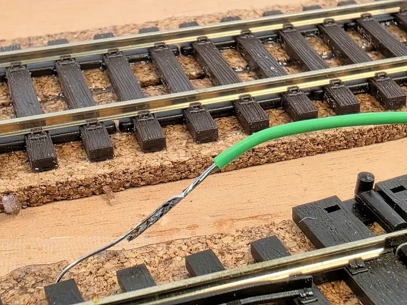
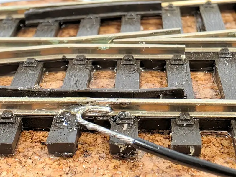
I usually cut the wires to size in small groups. I typically prepare between 5 and 10 wires to apply at the same time. I often see users stripping the wires short, which ensures that insulation is often visible. This can be done better, so strip the wires at least 1 cm before you pre-tin them. Then you won’t see any insulation after feeding the wires downwards. Regarding that feeding through, I also often see the hole to the bottom being made far from the solder joint. Drill the hole directly next to the solder joint between the sleepers; then they disappear completely and you won’t see anything of them later. After all, you only solder about 3-4 millimeters of the wire to the rails. The rest disappears into the wood.
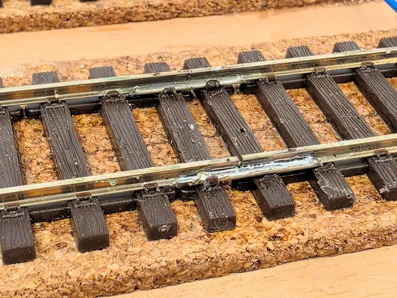
There is often a discussion about whether the rails should be soldered on the side or the bottom. This is a matter of technique, I think, alongside personal preference. I prefer to solder on the side afterwards. Then I don’t have any hassle with wires covered in glue. Also, I don’t have to think about this while laying the rails. And with the right soldering technique, you won’t see anything of that wire at all after weathering the rails.
Step 5: The soldering
Hot hot iron, literally and figuratively. But you can learn to solder by practicing it. I do follow a few rules from experience that give the best results:
Use of a good soldering station
I use a soldering station with a narrow tip 0.2 to max 0.5 mm. The advantage of a station is that the temperature is well adjustable and with a digital station, there is a load control on the temperature. That prevents a drop in temperature when you put the iron against the material. Metal also conducts heat, and with too great a loss, you get a “cold” solder joint.
Use flux
Because the heat from the iron quickly flows away into the material, you actually want to concentrate the temperature on a specific spot where you’re going to solder. The flow of the tin must be accelerated, and for this, you use flux. This prevents melted sleepers or other plastic. I don’t use flux pens; I find those far too expensive for soldering to rails. I use S65 from Griffon. And no, this is not S39! Be very careful with this!
S39 is flux for regular copper pipes which is quite aggressive. If you use this, it will eat away the rails over time. S65 on the other hand is an acid-free fluid for drinking water pipes, completely harmless then and removable with water. With 1 bottle, you can solder kilometers of rails, for the price of 1 syringe of flux which won’t get you through a kilometer of rails.
When I’m finished soldering and the wires are tucked away, I often brush the rails clean with Isopropyl alcohol. Then I remove excess flux that hasn’t dissolved due to the heat.
The right solder wire
Solder wire is also an important factor. I use lead-free solder with a rosin core anyway. And personally, I find a solder thickness of 0.5 mm the nicest. The thinner the solder wire, the better the amount of added tin can be controlled. With a thickness of 1mm, you quickly get too much tin on your workpiece.
Tip cleaner
Tips burn and tin does too. To keep the tip clean, I often wipe it clean in brass wool. And if the tin no longer wants to adhere to the tip, I put the tip in a container of TIPPY for a moment. This is stuff that burns the tip clean; it stinks enormously but works very efficiently.
Temperature of the iron
This is a personal choice; the lower the temperature, the longer it takes before the tin starts to flow. I hate this, so I literally bake. I solder at 450 degrees which is really hot; my tips also wear out quite quickly. I take this for granted, rather that than putting my iron on a workpiece for too long. Most vary between 350 and 450 degrees.
Applying the tin
Don’t feed the tin via the iron, but onto the material. Once it’s sufficiently heated by the iron, the tin will start to flow and then you know for sure that you have a good flow of the tin.
The practice
Today I soldered the wiring at the station. This can be seen at an accelerated pace in the timelapse reel. Normal speed is quite sleep-inducing. All in all, I was finished in 1.5 hours. Next time, I’m going to tuck the wires away to the underside of the wood and apply the section gaps. Once this is done, I can start tucking the wiring away to the electronics.
Did you enjoy this explanation? Then subscribe to my Youtube, Instagram, or Facebook channel, and leave a comment on this article! I’m happy to answer your questions 🙂
Cheers, Martin